User Tools
Table of Contents
Block Definition and Internal Block Diagrams
Modeling Blocks
- Edges with reference property (no arrow head), without reference property (arrow head)
- Fan out/in of flow
Block Definition Diagram
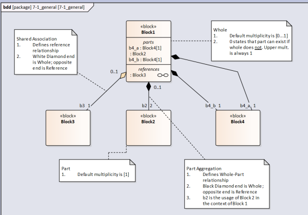
This is a Block Definition Diagram (bdd). It is commonly used to model structures.
Structures (i.e. a BOM) are modeled with Part Association (sometimes referred to as Composite Association) edges. These edges relate a Whole with a Part.
Note that the default multiplicity on the Whole end is [0…1]. The [0] means that if the Whole did not exist then the Part would still exist. If the multiplicity was [1] (it can not be higher than 1) then if the Whole did not exist the Part would also not exist.
Note that sometimes it is convenient to provide alternative hierarchies for systems. E.g. Electrical structure. In this case use Shared Association edge.
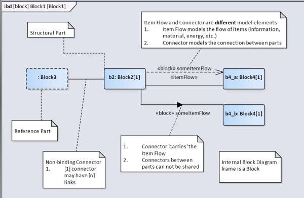
Internal Block Diagram
Multiplicities
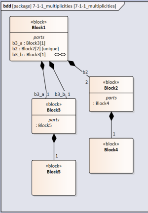
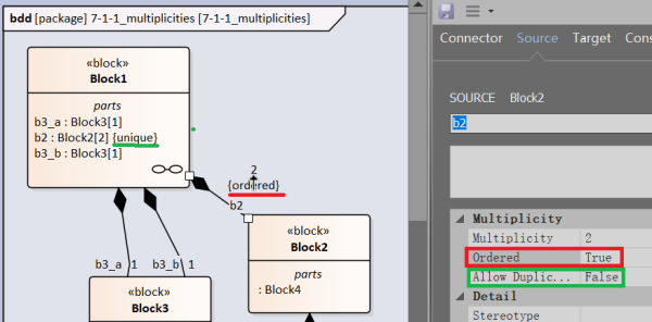
In the below diagram there are two usages of Block3 (b3_a and b3_b) in the context of Block1, each with a multiplicity of [1]. However the definition of Block3 also includes a part defined by Block5. How many usages of Block5 exist?
The answer is two. b3_a and b3_b each include a part defined by Block5.
In the case of Block2 it has a multiplicity of [2] in the context of Block1. This means that there are two Block2 parts in the Block1 whole. How many usages of Block4 exist?
The answer is also two. Even though the individual usages of Block2 have not been assigned a part name in each usage there exists one part defined by Block4.
The modeling program automatically assigns the {unique} property to Block2 if the upper limit multiplicity is greater than [1]
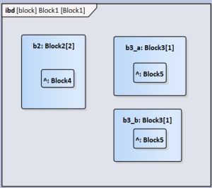
The resultant internal block diagram looks like this. Note that if the usage of Block5 was given a name the same name would appear within the two Block3 parts.
Ordered and Unique
Ordered states that the parts (if multiplicity > 1) are in a certain order, typically in a natural number order: 1, 2, 3 etc. To establish this property in the Connector Properties → Source set Ordered to TRUE (by default it is FALSE). The {ordered} notation appears below the multiplicity adjacent to the composite edge.
Unique states that within the set there are no parts that are the same. As mentioned this is automatically assigned to the part property in the whole block if the multiplicity > 1. To override this, in the Connector Properties → Source set Allow Duplicates to TRUE.
Namespace
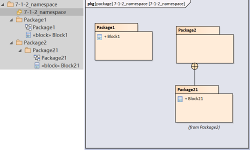
Namespace treats the package hierarchy analogous to a folder directory except the '/' (or '\' in Windows) is replaced with '::'. However semantics is simpler. In the below example Block1 and Block21 share a 'root' package '7-1-2_namespace' but are in different levels.
If Block21 were to be linked in the same package as Block1 then the block's name is qualified with the namespace resulting in a full name, Package21::Block21
I was expecting Package2::Package21::Block21 as Package1 (which contains Block1's bdd) can not 'see' Package21 but can see Package2
Nested Properties
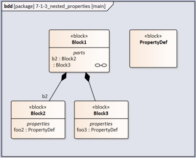
Property foo is typed by block PropertyDef. It appears as foo:PropertyDef. Block2 includes property foo2:PropertyDef and Block3 includes property foo3:PropertyDef.
Both Block2 and Block3 are parts of Block1
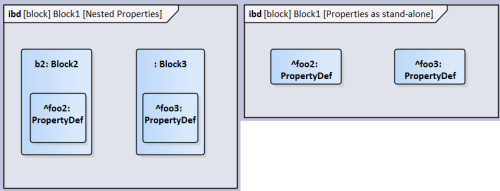
In the figure below, on the left, is the ibd of Block1 with properties nested in the parts. On the right is the ibd with the parts' properties shown without being nested in the parts.
Actually placing the part's properties on the diagram without the nesting parts (dragged from the model tree) brings the parts the same level as the parts. This operation is also linked to the qualified naming of the properties being unchanged. I was expecting foo2:PropertyDef → b2.foo2:PropertyDef and foo3:PropertyDef → Block3.foo3:PropertyDef
Association Blocks
How to use association blocks?? How to add constraints to these blocks
Association blocks are used to type connectors. To use:
In the block definition diagram toolbox choose 'Association Block'
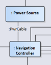
 Draw the relationship between the blocks you want to type an association block. Note that by default direction is not specified. Name the new block (in this example 'Power Cable')
Note that you need to make the association between blocks and not ports (proxy or full) if you want to type a connection
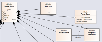
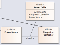 Draw a composition relationship between Power Cable block to the whole block ('Logical Rover')
 Select the association relationship. Give it a name ('PwrCable')
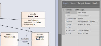
What is the difference between relationship block type and the standalone block type? Could 'Power Cable' block be the 'association class' of 'PwrCable'?
In the internal block diagram draw a connector between the two part properties you want to connect
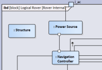 Right click connector → Advanced → Set Connector Type…
Choose the PwrCable association
 You've successfully type an association!
Reference Systems
You may want to create reference systems to organize the part structure in different ways. For example you may only be interested in the power sub system of the system, or the control sub system. In a typical BOM hierarchy parts are segregated by the physical location of parts which may defy a pan-system sub system such as power.
Assuming that you create a BOM like structure already you do the following
In a new BDD create a Block 'Power Sub-system'
Drag in existing Blocks that you want to include in this sub system. In the below example I have Power Source and Camera.
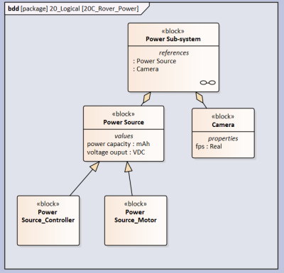 Use the 'Shared Association' relationship to connect Power Source to Power Sub-system. To create the relationship you start the drag from Power Source (source) to Power Sub-system (target). Notice that the blank diamond is at the Power Sub-system end. Note: Don't use the 'Reference Association' as the created relationship is weak and will not be useful in the following steps.

So what is the Reference Association used for?
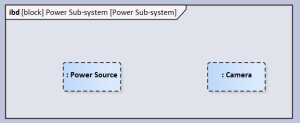
Now create a IBD with the Power Sub-system being the frame.
In the element tree drag the reference properties ': Camera' and ': Power Source' in to the IBD. You will notice that these properties have a dashed boundary which explicitly state that these properties are reference properties.
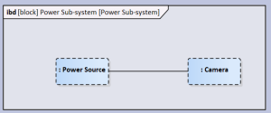
 Add a connector between the properties if there is necessary (assuming that there is actually a connector).
 Done
Done

