User Tools
Table of Contents
Block Definition and Internal Block Diagrams
Modeling Blocks
- Edges with reference property (no arrow head), without reference property (arrow head)
- Fan out/in of flow
Block Definition Diagram
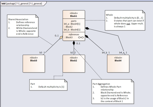
This is a Block Definition Diagram (bdd). It is commonly used to model structures.
Structures (i.e. a BOM) are modeled with Part Association (sometimes referred to as Composite Association) edges. These edges relate a Whole with a Part.
Note that the default multiplicity on the Whole end is [0…1]. The [0] means that if the Whole did not exist then the Part would still exist. If the multiplicity was [1] (it can not be higher than 1) then if the Whole did not exist the Part would also not exist.
Note that sometimes it is convenient to provide alternative hierarchies for systems. E.g. Electrical structure. In this case use Shared Association edge.
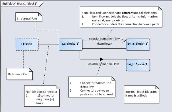
Internal Block Diagram
Multiplicities
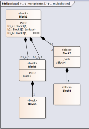
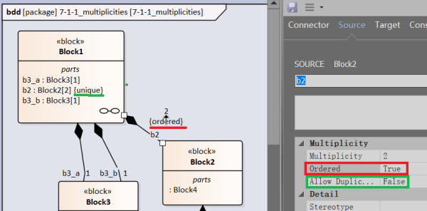
In the below diagram there are two usages of Block3 (b3_a and b3_b) in the context of Block1, each with a multiplicity of [1]. However the definition of Block3 also includes a part defined by Block5. How many usages of Block5 exist?
The answer is two. b3_a and b3_b each include a part defined by Block5.
In the case of Block2 it has a multiplicity of [2] in the context of Block1. This means that there are two Block2 parts in the Block1 whole. How many usages of Block4 exist?
The answer is also two. Even though the individual usages of Block2 have not been assigned a part name in each usage there exists one part defined by Block4.
The modeling program automatically assigns the {unique} property to Block2 if the upper limit multiplicity is greater than [1]
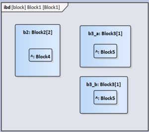
The resultant internal block diagram looks like this. Note that if the usage of Block5 was given a name the same name would appear within the two Block3 parts.
Ordered and Unique
Ordered states that the parts (if multiplicity > 1) are in a certain order, typically in a natural number order: 1, 2, 3 etc. To establish this property in the Connector Properties → Source set Ordered to TRUE (by default it is FALSE). The {ordered} notation appears below the multiplicity adjacent to the composite edge.
Unique states that within the set there are no parts that are the same. As mentioned this is automatically assigned to the part property in the whole block if the multiplicity > 1. To override this, in the Connector Properties → Source set Allow Duplicates to TRUE.
Namespace
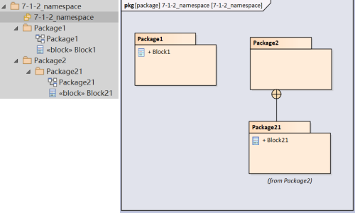
Namespace treats the package hierarchy analogous to a folder directory except the '/' (or '\' in Windows) is replaced with '::'. However semantics is simpler. In the below example Block1 and Block21 share a 'root' package '7-1-2_namespace' but are in different levels.
If Block21 were to be linked in the same package as Block1 then the block's name is qualified with the namespace resulting in a full name, Package21::Block21
I was expecting Package2::Package21::Block21 as Package1 (which contains Block1's bdd) can not 'see' Package21 but can see Package2
Nested Properties
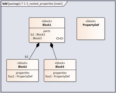
Property foo is typed by block PropertyDef. It appears as foo:PropertyDef. Block2 includes property foo2:PropertyDef and Block3 includes property foo3:PropertyDef.
Both Block2 and Block3 are parts of Block1
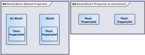
In the figure below, on the left, is the ibd of Block1 with properties nested in the parts. On the right is the ibd with the parts' properties shown without being nested in the parts.
Actually placing the part's properties on the diagram without the nesting parts (dragged from the model tree) brings the parts the same level as the parts. This operation is also linked to the qualified naming of the properties being unchanged. I was expecting foo2:PropertyDef → b2.foo2:PropertyDef and foo3:PropertyDef → Block3.foo3:PropertyDef
Association Blocks
How to use association blocks?? How to add constraints to these blocks
Association blocks are used to type connectors. To use:
In the block definition diagram toolbox choose 'Association Block'
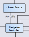
 Draw the relationship between the blocks you want to type an association block. Note that by default direction is not specified. Name the new block (in this example 'Power Cable')
Note that you need to make the association between blocks and not ports (proxy or full) if you want to type a connection
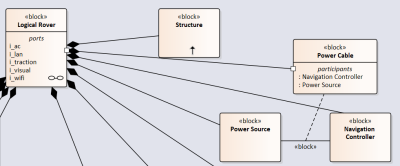
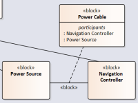 Draw a composition relationship between Power Cable block to the whole block ('Logical Rover')
 Select the association relationship. Give it a name ('PwrCable')
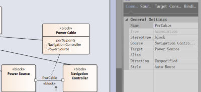
What is the difference between relationship block type and the standalone block type? Could 'Power Cable' block be the 'association class' of 'PwrCable'?
In the internal block diagram draw a connector between the two part properties you want to connect
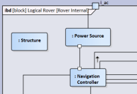 Right click connector → Advanced → Set Connector Type…
Choose the PwrCable association
 You've successfully type an association!
Block Behavior
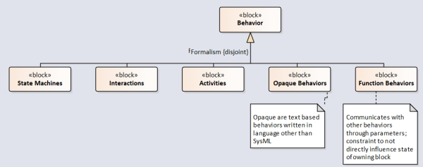
There are several formalisms that exist to depict behavior of blocks, chiefly State Machines, Activities and Interactions which would be allocated to the block with the use of the Allocation edge. Aside from these main formalisms it is possible for Blocks to directly own Opaque Behaviors and Function Behaviors. This section will look at the latter two in detail.
What are the pros and cons of directly owning behaviors?
Classifier Behavior / Main Behavior
Right click block → Properties → Special Action → Details There exists the Classifier Behavior field but do not know how to search for an existing behavior
A Block can own a behavior that initiates when the block is instantiated. The behavior may terminate before the instance is terminates.
Typically this is a state machine which calls activities/interactions. A block can only have one Classifier Behavior?
Owned Behavior
Provide detail on how to process service requests
How is this different to Operations?
Operations
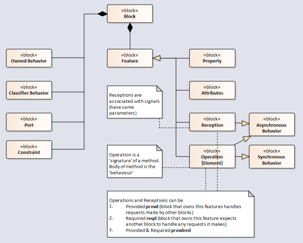
- Operation - Signature of a method. Must be owned by a block; have one or more inputs and output parameters and…
- Synchronous Operation … have only one return parameter
- Asynchronous Operation … have no return parameter
- Method - Some behavior that defines how an operation is executed
- Behavior - Body of method
- Reception - Some method associated with a signal (which is asynchronous). A reception designates a signal and specifies the expected behavioral response. The details of handling a signal are specified by the behavior associated with the reception or the classifier itself. The data carried by a (sent) signal is represented as attributes of the Signal. By declaring a reception associated to a given signal, a classifier specifies that its instances will be able to receive that signal, or a subtype thereof, and will respond to it with the designated behavior
- Provided Feature - A Feature that the block supports for other blocks to use
- prov «signal» SignalA means owning block provides a reception for SignalA
- Required Feature - A Feature that the block requires other blocks to support for its own use
- reqd «signal» SignalB means owning block requires a reception for SignalB
Items and Flows
Flow Properties
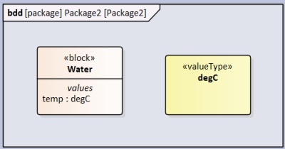
An item is information, energy or matter transferrable between blocks. Blocks can have flow properties to characterise what can be flow in/out of blocks. Flow properties can be typed by Value Types (e.g. tempC) or Blocks (e.g. Water, however the Water block will need to have value properties).
Item flows, on the other hand, are what actually flows between blocks.
Flow occurs between parts if
- flow properties in both parts are of the same type
- (OR downstream flow property is more general than the upstream flow property)
- direction shall be consistent (one property is inout, or both properties are opposite direction)
Below I create the item that I want to flow. Note that it has a value property of tempC.
In the BDD I add flow properties on Part blocks that are the conduits of what can flow. Note that the direction (in, out) is defined. In the Whole block I added two item properties which are the items that actually flow.
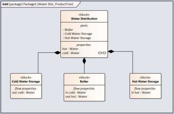
In the IBD I add connectors that connect the part blocks and item flows that carry the item properties. Note that the item properties shown on the connector is the item property of the Whole block.

Item Flows
In Association Blocks we covered how to define connectors. However what to do if you want to define the flows that occur on that connector? This is done with Item Flows.
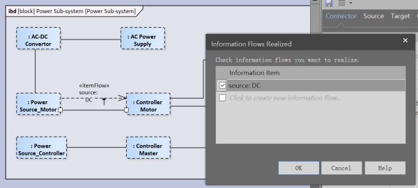
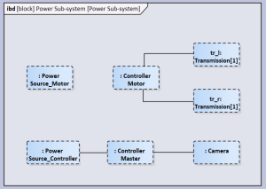 Following on from the Power Sub-system IBD add a connector between two properties. Call this connector 'someCable' (note that if we wanted to define the connector then we should use Association Blocks covered earlier). The connector name is elided.
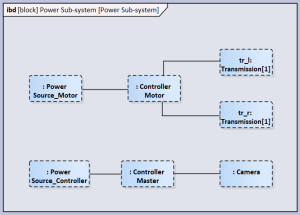 From the tool box use Item Flow relationship to create an item flow from ': Power Source_Motor' to ': Controller Motor'.
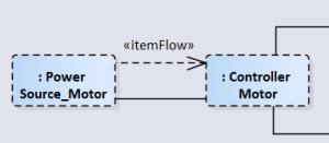
Type Item Flow by Classifier
Right click the information flow and Advanced → Information Items Conveyed… → Add
Find the Item Flow you want. It can be a block or (if simple) then a ValueType. In this case we want the item flow to be DC electricity which is modelled as a Block.

Right click on the connector and Advanced → Information Flows Realized..
Check the box for the information flow you just created. Click OK.
 Done
Done

Type Item Flow by Property
Double click on Item Flow. In Tags→Item Property search for upstream property. Typically this is a flow property.
Right click on the connector (which we named someCable) and Advanced → Information Flows Realized.. Check the box for the information flow you just created. Click OK.
Interfaces
The modeling of intra-system interfaces is of great importance as it is often the case the failure of systems occurs at such interfaces. SysML allows for different interface semantics:
- Port
- Full Port
- Proxy Port
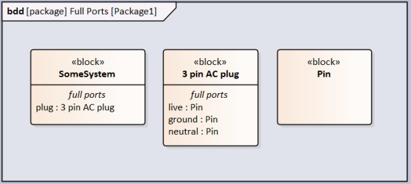
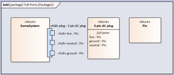
To create nested ports, e.g. live, neutral and ground pins on an AC plug, create a Block for Pin, create a Block for AC Plug. Add three ports to AC Plug, type each with Pin but call each a different usage (live, neutral and ground).
In the block that you want to own the AC Plug port, add a port and type it with AC Plug. Right clock the port and go Features→Interaction Points. Select the 3 pins and click ok. Now you're seeing nested ports
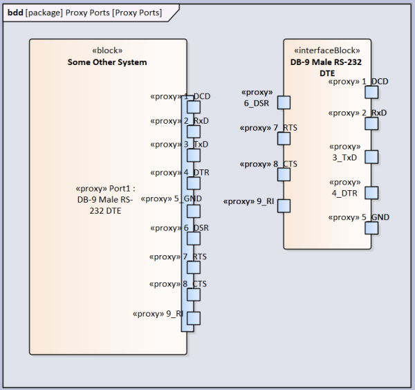
In the above example Full Ports are used for nested parts but Proxy Ports can also be nested as below
Full Port
Full ports are used for the design of physical ports. Use if part is on the BOM
- Equivalent to a physical port on the boundary of the parent block
- Can have nested parts and own behavior
- Can modify incoming/outgoing flows
- Can represent a physical part
- Other blocks can connect to a Full Port even if the owning block isEncapsulated=true
Proxy Port
Proxy ports are used to specify the enclosed system as a black box. Used as a model construct (e.g. for interfacing of non-BOM parts, e.g. torque)
- Proxy ports are not a part of the owning block
- Provides access (or act as a window) to selected owning block's features without modifying inputs/outputs
- Typed by interface block that specifies what features can be accessed
- Behavior Ports are a subset of proxy ports which only provide access to the owning block's behavior (as opposed to the owning block's internal structure).
How to use interface blocks to map onto properties of parent blocks
Connecting Proxy Ports
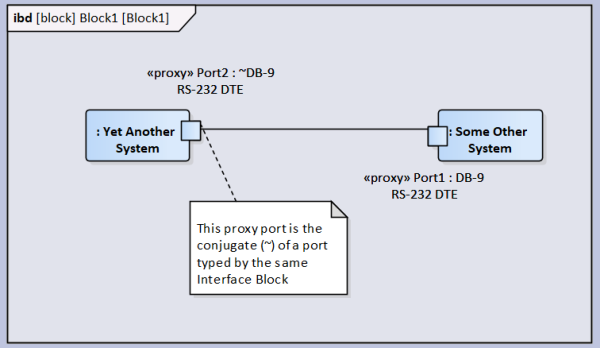
If connecting proxy ports to parts/full ports then the connection must be a binding connection.
Internal connections connect a port (port A) to a port/part (entity B) that is owned by the same block that owns by initiating port (port A). Internal connections between proxy ports to other ports/parts must be in the same direction (i.e. proxy port A is IN, proxy port B is also IN).
Conjugating Ports
Conjugating ports reuse a single interaction block for proxy ports that exchange similar items but in the opposite direction. One port is made conjugate to another, meaning that the direction of behavior features and flow properties are reversed relative to the other 'base port'.
Decomposing Ports and Connectors
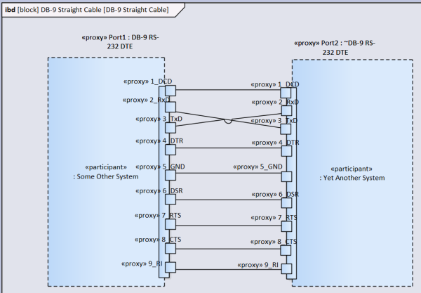
Connectors can be used to connect directly to nested ports. Alternatively, an association block can be used to specify the details of a connection. Not forgetting that the association block is connected from block to block the resulting association block (in the below case “DB-9 Straight Cable”) can be white boxed with an ibd of the association block.
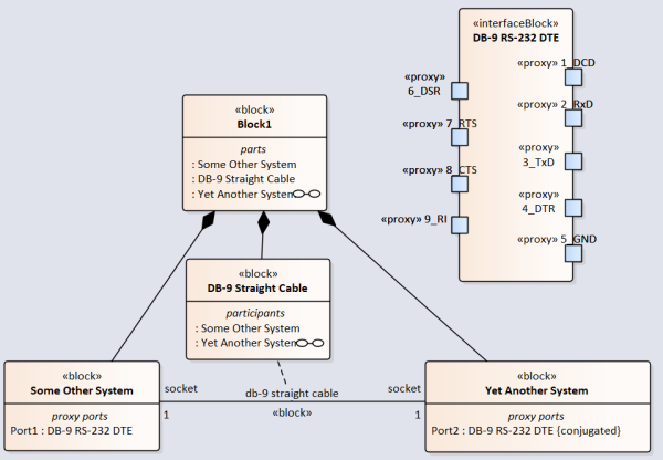
In the ibd of the parent block (Block1) the connection appears as :db-9 straight cable and only gives a high level view of the connection.

If you wanted to white box the connection itself then in the ibd of the association block the ports of the participating properties can be made to appear and connectors drawn between them.
Reference Systems
You may want to create reference systems to organize the part structure in different ways. For example you may only be interested in the power sub system of the system, or the control sub system. In a typical BOM hierarchy parts are segregated by the physical location of parts which may defy a pan-system sub system such as power.
Assuming that you create a BOM like structure already you do the following
In a new BDD create a Block 'Power Sub-system'
Drag in existing Blocks that you want to include in this sub system. In the below example I have Power Source and Camera.
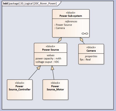 Use the 'Shared Association' relationship to connect Power Source to Power Sub-system. To create the relationship you start the drag from Power Source (source) to Power Sub-system (target). Notice that the blank diamond is at the Power Sub-system end. Note: Don't use the 'Reference Association' as the created relationship is weak and will not be useful in the following steps.

So what is the Reference Association used for?
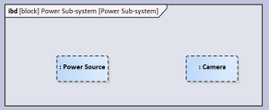
Now create a IBD with the Power Sub-system being the frame.
In the element tree drag the reference properties ': Camera' and ': Power Source' in to the IBD. You will notice that these properties have a dashed boundary which explicitly state that these properties are reference properties.
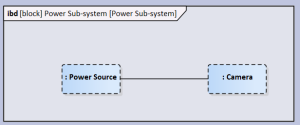
 Add a connector between the properties if there is necessary (assuming that there is actually a connector).
 Done
Done
Value Type
- In Unit instance it is not possible to reference an already existing quantityKind
- How to define literals for enumeration. Presently have used Attributes but not sure how to use it
Value Types, sometimes referred to as Data Types comes in three different flavors:
- Primitive (e.g. Real, String, Boolean)
- Enumeration (e.g. days of week)
- Structured (e.g. vectors)
We will first address Primitive types
Primitive Types
There already exist Primitive Types (e.g. Real, Number, String).
To create a custom Value Type typing a property of a block do the following:
Insert Quantity. In Element Properties → Run States enter relevant information
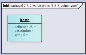
Insert Unit. In Element Properties → Run States enter relevant information. In quantityKind field enter the name of the created Quantity Kind.
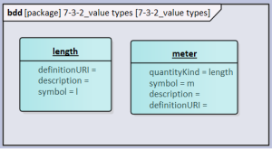
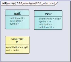
Insert Value Type. In Element Properties → SysML 1.5 reference the created Quantity Kind and Unit.
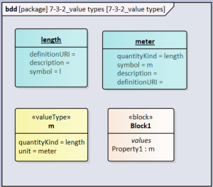
Insert Block. Drag Property to under the created Block. Select Property and then Element Properties → Property → Type. Select the Value Type you just created.
How to define a probability distribution for the property?
Enumeration
Is Attribute the right feature for Enumeration? How to use it?
Insert Enumeration to bdd canvas. Right Click → Features → Attributes. Add new attributes until list is complete.
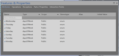
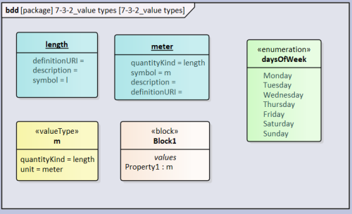
Insert Block. Drag Property to under the created Block. Select Property and then Element Properties → Property → Type. Select the Enumeration you just created.

Structured
Structured Value Types are a composite of simple Value Types and therefore you need to have tha simple types already defined. Add a new Value Type and add two Property under the Value Type. In each Property go Element Properties → Property → Type. Select the simple Value Type that you created earlier.
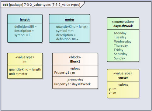
Insert Block. Drag Property to under the created Block. Select Property and then Element Properties → Property → Type. Select the structured Value Type you just created.
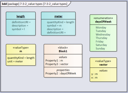
How to define initial values for structured value types?
Variants
Generalization Sets
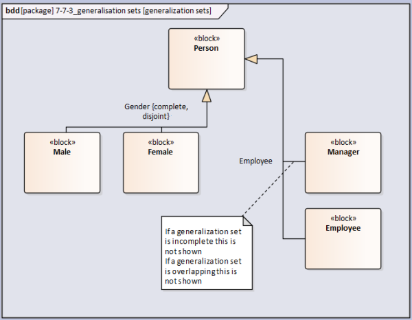
Simplest form of variation is with the use of generalization sets. By default a generalization set is overlapping and incomplete. See below example.
To create a generalization set do…
- Right click generalization edge → Advanced → Generalization Set → New
Disjoint is the opposite to Overlapping. Disjoint is the example of either a person is Female or Male, the person can not be both Female and Male. In the Employment generalization set it is Overlapping because somebody can be both a Manager and an Employee. Complete is the opposite to Incomplete. For Gender generalization set there are no other possibilities to Female and Male, therefore the set is Complete. However in the Employment generalization set there are other possibilities to Manager and Employee (e.g. Unemployed, Freelancer) and therefore Incomplete.
Inheriting and Redefining
Generalisation allows the child class to inherit properties (including parts) from the parent class. See the below example.
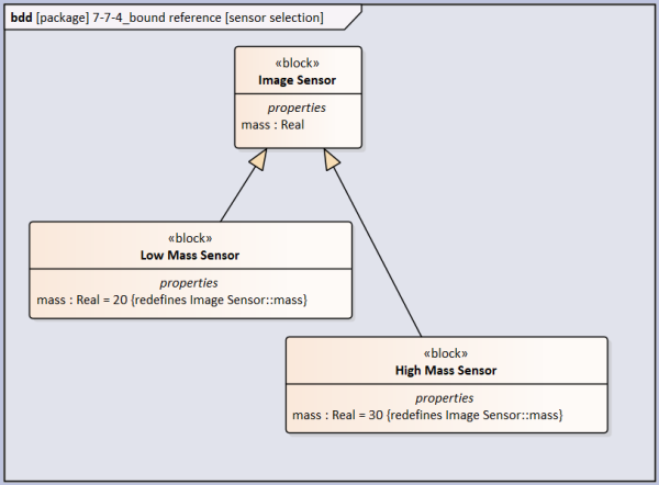
mass is a property of Image Sensor which is a general class for Low Mass Sensor and High Mass Sensor. Assuming that the parent block has the generic property already then after including the generalization edge on the child block:
- Right click Low Mass Sensor → Features → Parts/Properties
- Select Show Owned/Inherited
- The mass property (owned by Image Sensor) will appear
[If you want to redefine the parent's property - choose this if you want to modify the parent's property]
- Right click property (don't select it) → Redefine
- In Model Tree select the property now under Low Mass Sensor → Redefined/Subsetted → Redefined → Add..
- Chose the mass property that is under Image Sensor
- Now the {redefines Image Sensor::mass} appears in the Low Mass Sensor. In the Parts/Properties you will see a mass property owned by the parent class and the mass property (which is redefined) owned by the child class
- You can set an initial value for the redefined property or chose another less general type. This will not influence the property in the parent class
[If you want to inherit the parent's property - choose this if you want to copy the parent's property]
- Select the property. Prior to selection the mass property was owned by Image Sensor, now it is owned by Low Mass Sensor
- Now the property appears in the Low Mass Sensor block
- If the property in the parent class is modified (e.g. a value is assigned or the Type is changed, this will be reflect in the child class as well (this is not true if you chose to Redefine the property)
Bound Reference
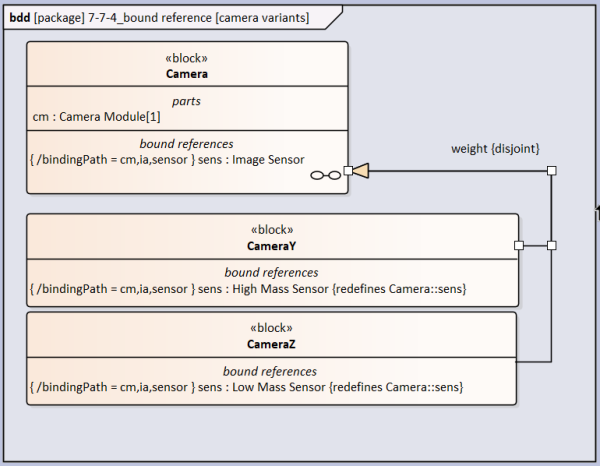
Generalisation alone is a simple and effective method to introduce variations. However it may the case that the variation is nested deeply within the block (e.g. a different image sensor provide variation to the whole camera) and the prior method would require the modeler to map out the entire tree to arrive at the part that is the cause of the variation. In this case the modeler can chose to use Bound References which are tailored to the task.
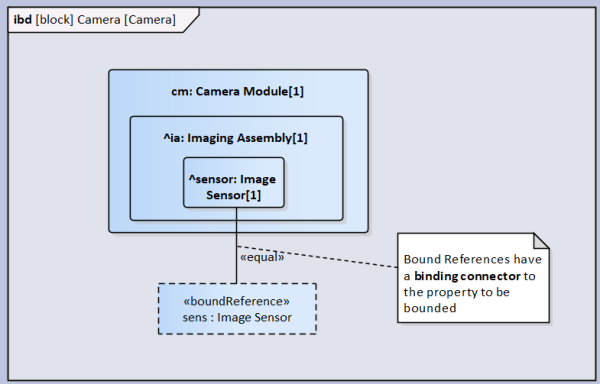
Include a Bound Reference into the ibd as shown below and add a binding connector between the bound reference and the part that is the source of variation. See below for an example.
Give the Bound Reference the same name and type. Also in the SysML 1.5 tab in the boundEnd find the property of the part (in this case sensor: Image Sensor [1])
Don't know why add the boundEnd property
To redefine the bounded property in the child classes (Camera Y and Camera Z are the child of Camera in this case) follow the instructions in Inheriting and Redefining. Select the more specific Type of the Image Sensor.
Property Specific Types
Don't know how to do this
Configurations with ID'd Blocks
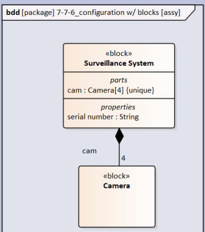
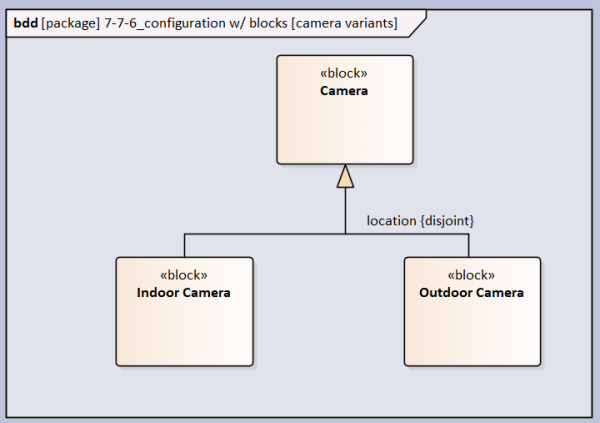
Assuming that a structure is defined and variants are typed (see below)
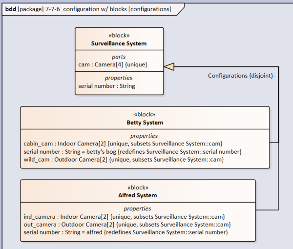
Then configurations are possible of the top level structure (or any level) as long as there exists one property which has a value unique to identify the configuration. In the below case this is serial number:String. In the Element Properties→Property the ID box is ticked.
I'm guessing that the unique identifier needs to be ID=TRUE.
Note that properties/values are redefined whilst parts that are made more specific (cam:Camera) are typed by a child type (Indoor Camera, Outdoor Camera) are subsetted. To subset a property follow the same procedure to redefine only in Redefined/Subsetted tab Add… from the Subsetted section.
Configurations with Instances
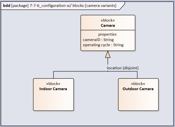
If the modeler only wants to change values to create a variant then can use Instances. Firstly I have added two properties to Camera (see below):
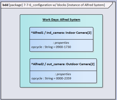
In a new BBD drag Alfred System block on the canvas and instead of selecting Link chose Instance (Object). After insertion of instance (note that the color is different and the name field is underlined) then assign a name to the Instance (e.g. Work Days) then right click → Features → Parts/Properties. Now the properties can not be further redefined. Select the property ind_camera:Indoor Camera. The property appears as ^/ind_camera:Indoor Camera. Give the property an identifying name. If it is renamed (e.g. Alred1) then it will appears are ^Alfred1/ind_camera:Indoor Camera
Do same for Indoor Camera, except this time select operating cycle:String.
After insertion of operating cycle:String notice that the name is dropped and appears as :String only. Whilst choosing the property, in Element Properties→Property→Initial: Define a new string and assign a recognizable name (in the below case: “opcycle”).
It appears that I can not insert Instance properties within an existing Instance object.

