Table of Contents
Survey of MBSE Methodologies
This page's structure follows closely that of of J.A. Estefan "Survey of Model-Based Systems Engineering Methodologies", INCOSE MBSE Initiative (2008) Rev. B.
Gaps that the below survey seeks to address to the 2008 survey include
- 2010 revision to Harmony/SE
- 2nd edition for Vitech MBSE Methodology (released 2011)
- 2012 release of JPL SA
- inclusion of SYSMOD
- inclusion of Functional Architecture for Systems
Ontology
- Language: A set of syntax and semantics
- Metamodel: A description of a model
- Method: Techniques for performing a task. “HOW” it needs to be done
- Methodology: Collection of related processes, methods and tools
- Process: A logical sequence performed to achieve a particular objective. “WHAT” needs to be done
- Tool: An instrument, when applied with the correct method, can enhance the efficiency of a task
Lifecycle Development Models
- Waterfall
- Spiral
- “V” Model
Acquisition Lifecycle Models
DoD
- Concept Refinement
- Technology Development
- System Development & Demonstration
- Production & Deployment
- Operations & Support
NASA
- Concept Study
- Concept Development
- Preliminary Design
- Final Design
- Fabrication, Assembly and Test
- Operations & Sustainment
- Disposal
ISO 15288
- Concept
- Develop
- Production
- Operate
- Support
- Retirement
Methodologies
Harmony/SE
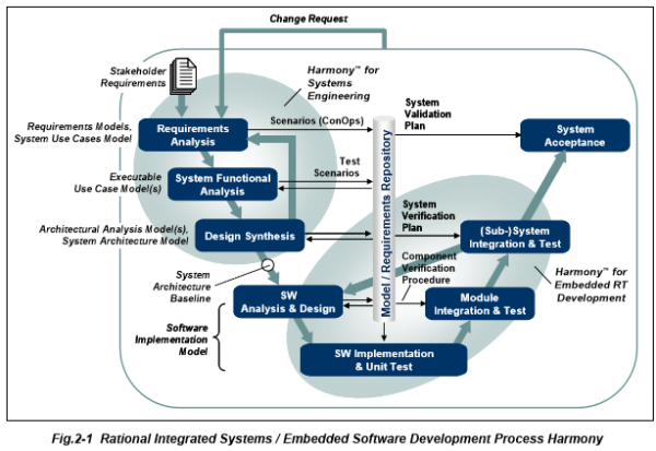
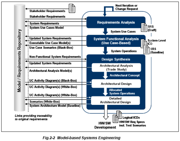
Harmony-SE takes a use case approach to modeling a system. Emphasis is on use of sequence diagrams and definition of operations and interfaces. Increments are use case based.
Methodology is available here. Methodology captured in a IBM Rational Harmony Deskbook Release 3.1.2 (2010).
The Harmony Process is split between “Harmony for Systems Engineering” and “Harmony for Embedded RT Development”. As you can see from the above figure the former focuses on the downwards side of the Vee development life cycle whilst the latter focuses on the upwards trajectory.
Objectives
- Identify / derive required system functionality
- Identify associated system states and modes
- Allocate system functionality / modes to a physical architecture
Development Activities
- Requirements Analysis
- Requirements Capture
- Definition of System Use Cases
- System Functional Analysis
- Main output is required operations to meet black-box use case scenarios
- Use case is translated into an executable model and the underlying system requirements verified through model execution
- Design Synthesis
- Architectural Analysis (Trade Study)
- Elaborate a concept for implementation of identified operations based on parametric analysis
- Architectural Design
- Allocated System Operations
- Allocation is verified through model execution
- After verification then architectural design may be analyzed with regard to performance analysis (reference previous measure of effectiveness metrics)
- Detailed Architectural Design
- Hardware / Software Design
Object-Orientated Systems Engineering Method (OOSEM)
Closely follows the recursive nature of the Vee life cycle development approach. Adopts Integrated Product Development (IPD) team.
To view the model download the zip file, extract files and then select oosem_process_baseline_yyyymmdd/index.htm
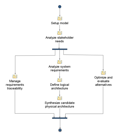
Once the html model is loaded click on “Specify and design system” and then you will see the OOSEM process chart. As of writing the latest version is baselined as OOSEM Process Baseline 1/2020.
Objectives
- Capture and analysis or requirements and design information to specify complex systems
- Integration with object-orientated software, hardware and other engineering methods
- Support for system-level reuse and design evolution
Development Activities
- Set up model
- Analyze stakeholder needs
- Captures as-is state, limitations and potential improvement.
- Analyzed using causal analysis techniques to determine limitations therefore derive mission requirements for the to-be system
- Mission requirements are provided as
- Mission objectives
- Measure of Effectiveness
- Top-level use case and scenarios
- Design system requirements
- System is modeled as a black box.
- Scenarios are modeled as activity diagrams with swim lanes
- Requirement change is evaluate as risk and flexibility is built in
- Define logical architecture
- Decompose and partitioning the system into logical components that interact to satisfy system requirements
- With a logical architecture the system design is more resilient to requirements change and is technology neutral
- Synthesize candidate allocated architectures
- Each logical component is mapped to a system node to address how the functionality is distributed
- Requirements for each system element are traced to system requirements
- Optimize and evaluate alternatives
- Parametric models are used to analyze and optimize performance across a range of criteria (safety, reliability, cost)
- Criteria and weightings are traceable to requirements and measure of effectiveness
- Monitor Technical Performance Measures
- Identify potential risks
- Validate and verify system
- Development of plans, procedures and methods
- System level use cases, scenarios are primary inputs to the development of test cases and associated verification procedures
IBM Rational Unified Process for Systems Engineering (RUP SE)
It was not easy to find a document that lays out what RUP SE is about. I found "Rational Unified Process" Rational Software White Paper TP026B, Rev 11/01 but it is a generalization of RUP SE.
Eventually found the below source material:
- Cantor M, “RUP SE: The Rational Unified Process for Systems Engineering” IBM Rational Software (2001). Accessed on September 8th, 2020 here. Overviews RUP SE Version 1.0
- Cantor M, “Rational Unified Process for Systems Engineering, Part 1: Introduction RUP SE Version 2.0” IBM Rational Software (2003). Accessed on September 8th, 2020 here
- Cantor M, “Rational Unified Process for Systems Engineering, PART II: Distinctive Features” IBM Rational Software (2001). Accessed on September 8th, 2020 here
- Cantor M, “Rational Unified Process for Systems Engineering, Part II: System architecture” IBM Rational Software (2003). Accessed on September 8th, 2020 here
- Cantor M, “Rational Unified Process for Systems Engineering, Part III: Requirements analysis and design” IBM Rational Software (2003). Accessed on September 8th, 2020 here
Based on the above SUP SE is baselined as Version 2.0, last updated in 2003.
Objectives
- Follow industry standard definition of systems
- Adopt blackbox and whitebox representation
- Blackbox representation is described in System Specification
- Whitebox representation is described in System Architecture
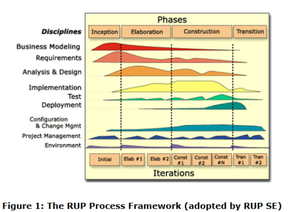
- Apply the RUP framework to systems development
- Lifecycle - focus on removing risks by adopting phases (Inception, Elaboration, Construction, Transition)
- Iterations - Iterative development process
- Disciplines - RUP takes into account the following disciplines
- Business Modeling
- Requirements
- Analysis & Design
- Implementation
- Test
- Deployment
- Configuration & Change Management
- Project Management
- Environment
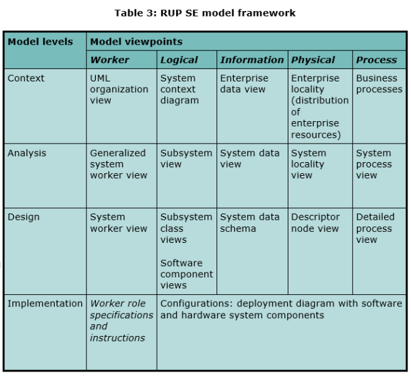
- Extend the RUP 4+1 architectural model into the RUP SE model framework
- RUP SE provides for the following viewpoints (can be extended to others)
- Role (RUP SE calls this 'Worker') - concerned with roles and responsibilities
- Logical - concerned with logical decomposition
- Physical - concerned with physical decomposition
- Information - concerned with how information is stored and processed
- Process - concerned with threads of control
- RUP SE sets out four model levels
- Context - system and its actors
- Analysis - system partitioning in each viewpoint to establish conceptual approach
- Design - realization of the analysis level
- Implementation - realization of design level
- Employ UML as modeling language
- Provide tool assets - essentially maintaining a plug in to IBM's Rational Software
- Maintain all model levels as a program asset - essentially maintaining traceability of low fidelity and high fidelity systems
Development Activities
- Start with Use Cases, i.e. how the system delivers value to / responds to Actors
- Treat system as a blackbox which has measures of effectiveness / budgets to meet Actor's need
- Develop whitebox representation of the system of how it will meet the operations defined by the blackbox representation
- RUP SE has Locality and Process as attributes of the whitebox representation. Locality is where the operation is hosted, Process is what executes the operation.
- Specify subsystem use cases.
- Visualize interaction of Actor with Process with a sequence diagram. Helps to identify whether processes can be combined if significant interaction between them.
- Visualize interaction of Actor with Localities with a sequence diagram. Shows dataflows between assets, helping to define communication protocols.
- Rinse and repeat.
Vitech MBSE Methodology
The source for the Vitech MBSE Methodology is D. Long & Z, Scott “A Primer for Model-Based System Engineering”, Vitech Corporation, 2nd edition (2011). This is available for download here.
Objectives
The design space includes three systems (a simplification of J. Martin's seven systems)
- Designing System
- System Under Design - solves a problem
- Context System - users of the system, environment, other interacting systems
Development Activities
Vitech Methodology describes main activities (Requirement Analysis, Functional Behavior Analysis, Architectural Synthesis) addressing, respectively, the domains of Requirements, Behavior, Architecture, Verification and Validation.
- Requirements Analysis
- Explore stakeholder needs creating a statement of system functionality
- Increase granularity of system behavior (that realizes need) and therefore increase specificity of requirements
- Functional Behavior Analysis
- Addresses (a) what the system must do in order to answer customer's need and (b) how well the system must perform these functions (i.e. measure of effectiveness)
- Construct logical model
- Architectural Synthesis
- Development of the physical model
- Allocating logical model to the physical model
- Trace requirements (through the logical mode) to the physical model
- Validation & Verification
JPL State Analysis (SA)
Sources for this methodology include
- D. Wagner, “An Ontology for State Analysis: Formalizing the Mapping to SysML”, IEEE (2012). Accessed on September 10th, 2020 here.
- D. Wagner, “An Ontology for State Analysis: Formalizing the Mapping to SysML”, Presentation to IEEE Aerospace Conference (March 2012). Accessed on September 10th, 2020 here.
JPL State Analysis…
- provides a methodology to design complex control systems
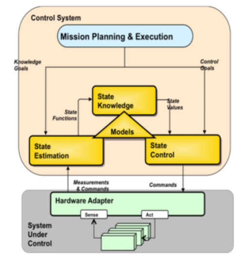
- Typical architecture is as below
- Mission Planning & Execution supplies Control Goals to State Control
- Mission Planning & Execution supplies Knowledge Goals to State Estimation
- State Estimation supplies State Functions
 to State Knowledge
 - State Knowledge supplies State Values to State Control
- Models bridges State Estimation, Knowledge and Control
- State Control supplies Commands to Hardware Adapter
- Sense (sensors) and Act (actuators) are ports to Hardware Adapter. Hardware Adapter is child to System Under Control
- Actuator creates changes which influences Sensors
- Hardware Adapter supplies Measurements & Commands to State Estimation
Rationale
- As system complexity grows it is not possible to manage a system based on subsystem-level functional decomposition, the web of interactions are too great
- There is a gap between requirements on SW specified by system engineers and the implementation of these requirements by software engineers, leaving open the possibility of misinterpretation of system engineer's intent
Objectives
- Facilitates system engineers to precisely express design intent in a tool that actively ensures consistency
- Clear distinction between Control System and System Under Control
- Provide a methodology for
- Discovering and documenting states of a system
- Modeling behavior of state variables and relationships between them
- Capturing mission objectives in detailed scenarios motivated by operator intent
- Keep track of system constraints and operating rules
- Describing methods by which objectives will be achieved
Development Activities
- The foundation of the JPL SA methodology is the control system and the system under control are explicitly different. This separation is formalized in an ontology which is written in OWL2. JPL used Protege as the editing environment.
- This ontology is mapped to SysML artifacts using Query/View/Transformation (QVT), a model-to-model transformation standard by OMG.
- A context diagram (block diagram) includes Analysis Context with parts System Under Control and Control System
- In a state effects diagram (=internal block diagram) map the relationship between different state variables contained within the context. Use affects and affectedBy relationships.
- Define mathematical relationships between State Variables with parametric diagrams
- Control System is designed. A State Variable has only 1 Controller and (may) have only one Estimator
- The HardwareAdapter is modeled to be an interface between the Control System and System Under Control. Measurements flow from System Under Control to Control System, Controls flow the other way.
- Goals are elaborated as (typically) stereotyped use cases whilst the temporal aspect of goals is defined as constraints and analyzed in parametric diagrams.
